
We all know that electric vehicles are powered by batteries. User behavior while driving electric vehicles, however, such as starting the car, pressing the accelerator and hitting the brake (regenerative braking) highly affects battery performance, and even its cycle life. Therefore, the United States Advanced Battery Consortium (USABC) has made corresponding regulations and forced EV batteries to pass the Variable Power Discharge Test before they are released to the market. Thus, “Drive Simulation Test” is used to assess the performance of EV-used batteries in actual on-road driving conditions.
There are two well-known drive simulation test standards announced by USABC, and they both use power as a parameter to simulate actual driving load.
1. The FUDS (Federal Urban Driving Schedule) : a repetitive 1372-second test profile
2. The DST (Dynamic Stress Test) : a repetitive 360-second test profile
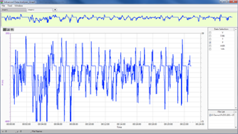
FUDS Cycle Test Figure Obtained Using MCL2 Series
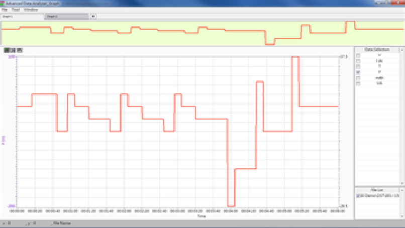
DST Cycle Test Figure Obtained Using MCL2 Series
Besides variable power discharge, variable current discharge and pulse discharge happen frequently in real-world practices as well. To support more comprehensive test requirements, Chen Tech battery test equipment builds in FUDS, and DST test standards in the system, and also allows users to import battery charge/ discharge patterns from a real test drive.
To conduct FUDS, DST or other drive simulation tests, at least 3 critical technologies should be implemented:
- Since all input variables in a drive simulation test change rapidly, the equipment should be able to record test data such as voltage, current, and capacity with even higher frequency to facilitate data analysis.
- The switch time between discharge (pressing the accelerator) and charge (hitting the brake) of the battery is less than 1 second in actual driving conditions. Therefore, the test equipment should be able to perform rapid switch between charge and discharge to flawlessly simulate actual driving scenario.
- Quick current response time (rising/ falling time) is necessary to meet corresponding current output requirements in drive simulation tests.
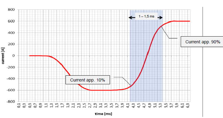
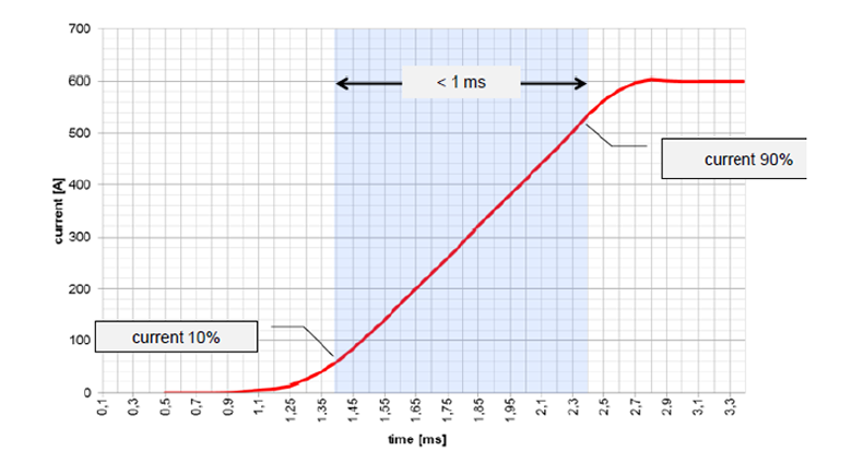
The above testing figures are obtained using PBT 1000 800V/600A System
CTE PBT 2000 Series and MCL2 Series support full drive simulation functions, and the key indicators for these two systems are as follows:
| Key Indicators | PBT 2000 Series | MCL2 Series |
| Charge/ Discharge Capability | Up to 500kW, 1000V, 1000A | Up to 800V, 1500A |
| Data Recording Time | 100ms (Option: 10ms) | 100ms (Option: 10ms, 1ms) |
| Switch Time between Charge and Discharge | 2ms | 20ms |
| Current Response Time (10%→ 90%) | 2ms | 10ms |

